Kirchhoff’s Law
Kirchhoff’s law was stated in 1824 by Gustav Robert Kirchhoff, a German physicist who specialized in electrical circuits. The law of circuits or also known as the law of meshes has the possibility of being derived from Maxwell’s equations.
These two Kirchhoff laws are the same laws that rely on the charge found in electrical circuits as well as the principle of energy.
Kirchhoff’s law is composed of two laws:
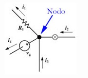
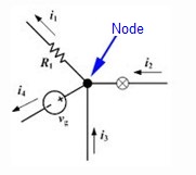
- The law of nodes or currents = the sum of the currents at a particular node (junction point of two or more conductors) is equal to the combined sum of the outgoing currents.
Conservation of charge: ∑I in = ∑ I out.
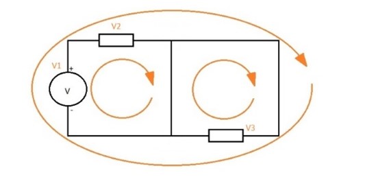
- The law of circuits or voltages= The law of circuits can also be called the rule of grids or voltages. This law states that the algebraic sum of the voltages in a closed circuit is equal to 0.
Conservation of energy: ∑ fem = ∑ (IR )
Although there are officially 2 laws, because of the relationship found in the difference between current and attention.
Node law

i2 + i1 = i3 + i4
Circuit law

V1 + V2 + V3 + … Vn = 0
Advantages of Kirchhoff’s law
Kirchhoff’s law allows us to calculate currents and voltages easily. On the other hand, the simplification and analysis of closed circuits can be modified.
Applications of Kirchhoff’s law
The two laws are used in electrical engineering to obtain the currents and voltages at a given location in an electrical circuit.
Kirchhoff’s equation gives us the possibility to calculate the enthalpy increase at different temperatures. Depending on the temperature we can find different types of enthalpy such as enthalpy of formation, enthalpy of decomposition, enthalpy of combustion, and enthalpy of neutralization. The calculation of enthalpy is an equation that is important for thermodynamics.
According to Kirchhoff’s law of thermal radiation, it is determined that the emittance, as well as the absorptivity of a surface, is equal.
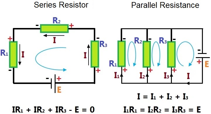
To determine the sum of n resistors by Kirchhoff’s law we can find series and parallel resistors.
In series resistors, they are connected one after the other, as shown in the picture, so that if one of them stops working, the others do too. On the other hand, in the parallel resistor they have the same input, but different output; so if one stops working the others are not affected and continue working.
